Cell-internal sensor technology

Battery cells with internal reference electrodes

To increase the safety of Li-ion batteries, knowledge of the actual electrode potential is desirable. In a 2-electrode system, where only the voltage difference between the anode and cathode is known, one of the electrode potentials could still be outside its safe limit. In this case, a normal voltage difference between the electrodes masks the violation of the safe potential limit of one electrode, as shown in Figure 1.

In a system with a reference electrode, the electrode potentials can be directly monitored and the battery management system is able to terminate battery operation. This can prevent common problems of lithium-ion batteries, such as lithium dendrite formation or the occurrence of oxidation processes at the cathode.

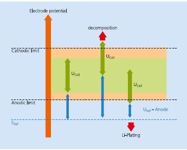
Figure 1: Schematic representation of the potential ranges in an electrochemical ce /1. If the potential of both electrodes is shifted, the potential limits can be exceeded although the ce/1 voltage is inconspicuous.

Other advantages:

  • longer battery life
  • increased energy or power density
  • fast charging
  • operation at lower temperatures

Situation before the project

Nevertheless, lithium-ion batteries equipped with thermocouples and/or additional reference electrodes are hardly described in the literature and even less available for purchase. Lithium metal is very common as a reference electrode in scientific experiments, but is not usable for commercial cells.

In order to independently determine cell electrode potentials, the reference electrode must have a defined stable electrochemical potential, negligible voltage drift, chemical inertness within lithium ion technology, and no aging effects.In addition, as a requirement of the manufacturer, it must be compatible with cell production processes. 

Materials such as Li4Ti5O12 (LTO) or LiFePO4 (LFP) with a broad two-phase equilibrium provide a very stable potential plateau and also meet the above requirements . These materials can be used as reference electrodes in lithium-ion cells, especially in customized cells.

Methods and results

Figure 2: Results of the characterization of an NMC/graphite cell with an internal reference electrode (LTO) Figure 2a: Voltage profile of ce/1, anode potential monitored against the reference potential. Figure 2b: Voltage profile of ce/1, cathode potential monitored against the reference potential Figure 2c: Converted anode (graphite) potential to a potential against Li/Li+. Figure 2d: Enlargement of the green outlined part of the potential curve in figure 2c and its first derivative.
Figure 3: Evolution of the temperature distribution in a rectangular pouch-ce/1 (151 x 200 mm2) during 2C charging, measured with temperature sensors inside the ce/1. The different graphs show the temperatures at SOC = 0%, 15%, 30%, 45%, 60%, 70%, 80%, 90%, 100%.

The test cells (NMC / graphite) were fabricated using ISIT's lamination technique in a bicell design (5.6 x 3.1 cm 2), with an internal LTO reference electrode (0.8 x 1.4 cm 2) located at the cell bottom between the separators at a sufficient distance from the cell stack. This design was confirmed by computer simulations performed by the project partner ITWM.

The cells were formatted according to a standard procedure, then the reference electrodes were charged to a mean state of charge (SOC) of LTO with respect to the cathode to ensure a constant reference potential.

The cells were then cycled at 0.5 C between 4.2 and 3.0 V, with the reference voltage monitored against both the graphite anode and the NMC cathode. The corresponding Munterelectrode voltage was calculated by Ucell = Uc-Ref + UA-Ref.

The measurements (Figs. 2a, 2b) show a well reproducible voltage profile and the observed voltage ranges (NMC vs. LTO = 2.8 - 1.8 V, LTO vs. graphite = 1.5 - 0.9 V) are in agreement with the theoretical values. Moreover, the voltage profile resembles the graphite electrode voltage profile to the well known formation stage during lithium intercalation in graphite. To confirm this, the graphite reference voltage profile (vs. LTO) was converted to a potential profile vs. Li/Li + (Figure 2c; detailed magnification of the discharge domain in Figure 2d, top and its first derivative in Figure 2d, bottom). The minima (Figure 2d, arrows) indicate the plateaus of the lithium stage and agree very well with literature values.

Conclusion

An integrated LTO reference electrode enables independent and reliable determination of the real anodic as well as the cathodic electrode potential. This allows undesirable and often safety-relevant cell states (e.g. lithium plating) to be avoided. The presented reference electrode is constructed from typical LIB materials using common coating techniques. Thus, the production of LIB cells with reference electrodes is possible in today's established production process and allows a fast commercialization.

Indoor temperature measurement

The local temperature inside lithium-ion batteries is also a valuable input parameter for the battery management system to minimize cell aging and avoid a safety-relevant increase in cell temperature. As part of the Topßat project, commercially available temperature sensors were tested for their suitability for temperature monitoring in laminated lithium-ion batteries. Key criteria were small size, high accuracy, and ease of installation in the batteries with low battery and sensor failure rates. Two sensor types were found to be suitable, allowing easy installation with low failure rates (no failures), each with advantages and disadvantages:

1. NTC thermistor:

(M cro-BetaCHIP 10K3MCD1 measurement specialties)

  • acceptable spatial dimensions (cylindrical Bo dy 0 0.5 mm x 3.2 mm)
  • high accuracy of ±0.42 K with a highly accurate resistance meter

2. Miniature thermocouple (TC Direct Miniature Ther mocouple)

  •  very small dimensions (0 0,25 mm)
  •  metal sheath can cause inte rneal short circuits (has not occurred)
  • low accuracy of ±2.0 K with corresponding temperature transmitter