 Fraunhofer Institute for Silicon Technology
Lars Ratzmann & Jörg Albers
From sketch to demonstrator
Sounds a little like something from days gone by, but in the age of artificial intelligence, autonomous driving and quantum computers, it is still the first step when it comes to realizing an initial idea, writing a piece of paper and something when building or implementing an application-oriented demonstrator. This sketch is the basis for the further design process. Based on this idea, a 3D model is used to give the whole thing precise contours, fix the dimensions, introduce further innovative aspects and, last but not least, to make the basic structure visualizable and imaginable for the development team. Already at this stage, errors can be detected early on and naturally avoided.
Fraunhofer ISIT develops and manufactures a wide variety of MEMS devices for optical applications. For these mostly active devices, some form of electronics is always necessary to bring the filigree silicon structures into a defined working area. A further, not insignificant aspect is the application or the integration into an existing or newly developed optical system. Thus, we face three challenges in order to obtain a practical, functional and application-oriented demonstrator in the end. The MEMS device, the electronics and finally the integration into the application.
This development process is very iterative. Especially for the different MEMS systems, individual solutions are required to ensure full functionality at all times.
Our current development focus is on drive systems for piezoelectrically driven quasi-static MEMS mirrors, while the system know-how for resonant MEMS mirrors has already reached a level of maturity and is entering the market through our spin-off company.
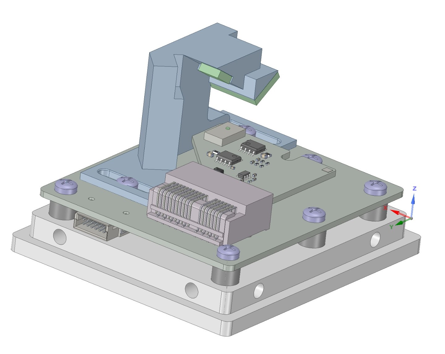
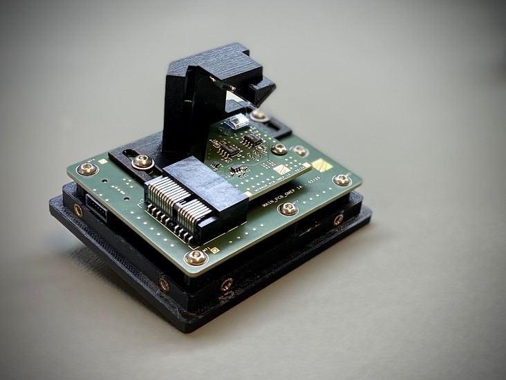
The example in the upper left corner of the figure shows the 3D model of a MEMS scanner based laser projection head for dynamic image content with its basic electrical and mechanical components. Next to it on the right is the final demonstrator as it is used in practice. This research result is part of the funded project "Smart Window". The objective is to supplement bridge windows in shipping with augmented reality in order to fade navigational information into the field of vision of bridge personnel and thus to superimpose reality with virtual objects.
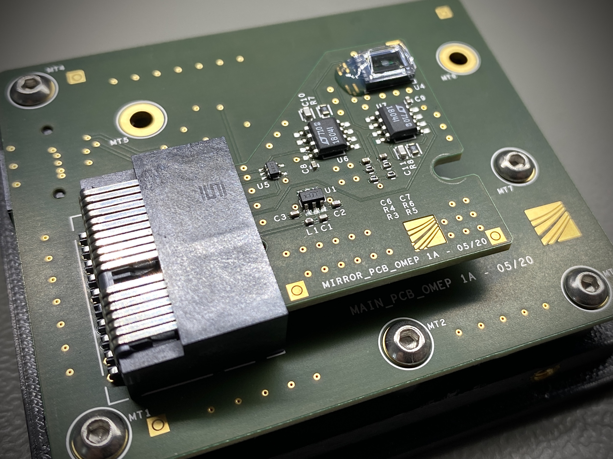
The figure shows the electronics of the projection head in close-up and especially the encapsulated and protected assembly in form of the 2D MEMS scanner on the top right of the MIRROR-PCB. The coupled, intensity-modulated laser beam is deflected via the two oscillating axes and draws the image plane onto the corresponding projection surface, in this case the bridge window. The electronics on both boards control and stabilize the scanner.
The present demonstrator from the research project presents the functionality for the corresponding intended application scenario and reflects the aspects and challenges in the development, as already explained above.