 Fraunhofer Institute for Silicon Technology
Saskia Lange und Helge Schimanski
In-situ X-ray analysis during the soldering process
At Fraunhofer ISIT there is the possibility to observe a reflow soldering process in-situ in an X-ray facility in order to visualize the pore formation during a soldering process.
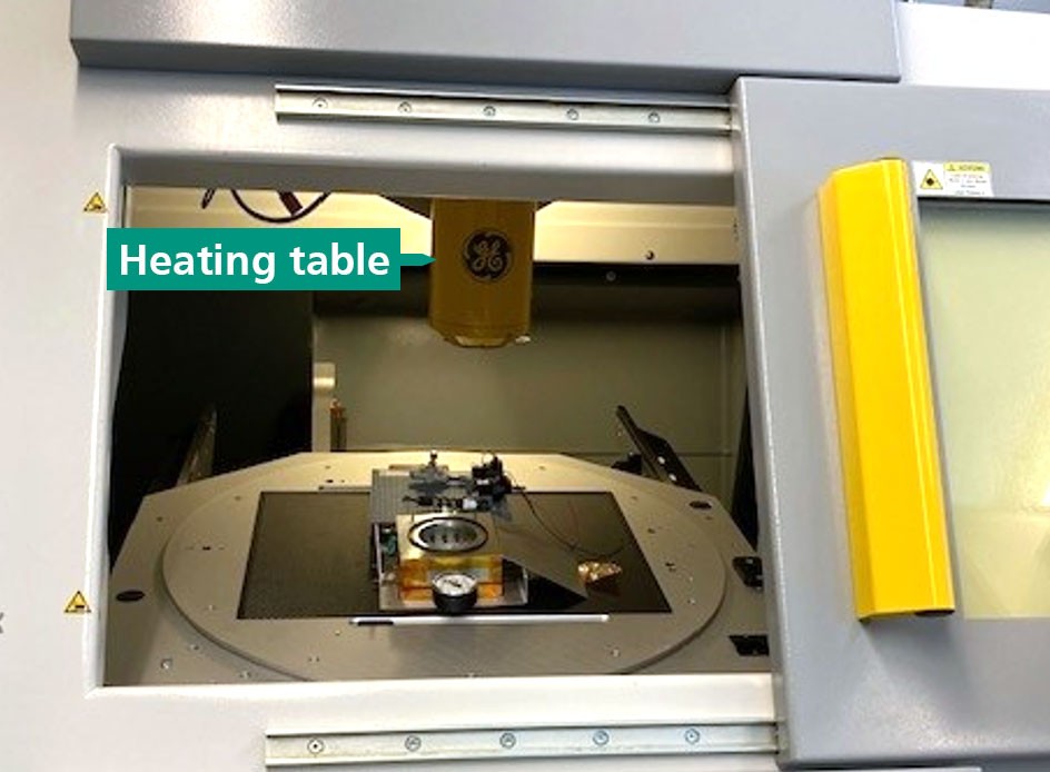
Figure 1: Heating table in the X-ray system
Pores in solder joints are a recurring topic when it comes to electrical load capacity, heat dissipation and reliability of electronic assemblies. In order to demonstrate the formation of pores during a soldering process, Fraunhofer ISIT offers the possibility to observe a reflow soldering process in situ in an X-ray facility. For this purpose, a substrate (e.g. ceramic carrier or FR4 circuit board) is printed with a solder paste, equipped with the component to be investigated and placed on a heating table in an X-ray system (Figure 1) and the soldering process is carried out. The maximum sample size here is approx. 4cm x 5cm. The exposure window (viewing area) during the soldering process is approx. 1.5cm x 1.5cm.
Procedure
The sample chamber is closed by means of an aluminum lid (Figure 2), evacuated and then flooded with nitrogen.
Alternatively, the chamber can be operated under vacuum to mimic a vacuum brazing process. When a defined vacuum is reached, the heating program is started manually. In this process, the heating table begins to heat up to the desired peak temperature with a predefined ramp, and the temperature-time profile specified in advance individually set in the program is run down. Both saddle and linear profiles can be simulated.
The heating system of the table and the X-ray system are controlled separately, so that X-ray radiography can be started at any time. The brazing process can now be viewed online in the X-ray system. During the reflow soldering process, both X-ray videos and individual photos can be recorded. The melting process and the formation of pores in the solder can be clearly seen in the live image. At the end of the set holding time in the peak phase, the heating is switched off and the heating chamber is cooled down by flooding with nitrogen. At the desired time, the radiographic process is manually terminated on the X-ray system. Afterwards, the images can be evaluated.
If you want to analyze your soldering process in more detail and e.g. compare different solder pastes and/or component/substrate combinations, please feel free to contact us.
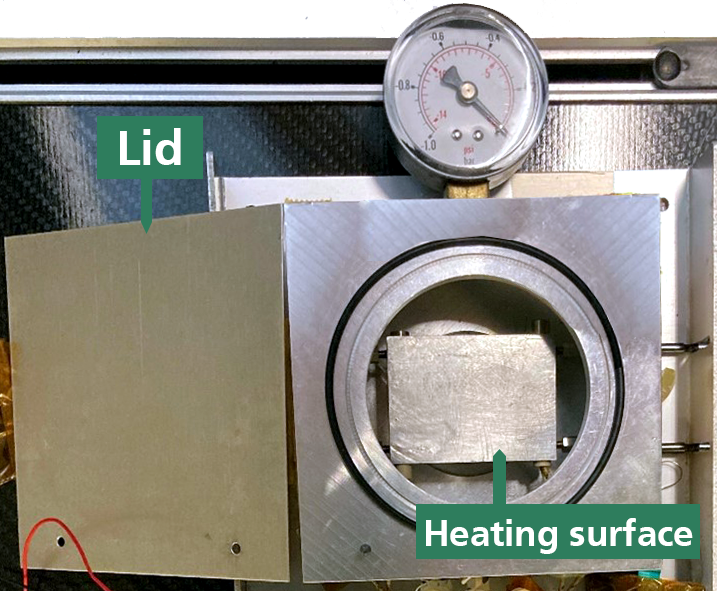
Figure 2: Heating table with lid leaning on the left side