 Fraunhofer Institute for Silicon Technology
Mario Reiter
Measurement of the surface resistance
Ionic impurities can lead to electrochemical migration (ECM) in the presence of potential differences under the influence of moisture and thus ultimately to failure of the electronics. In particular, the application of higher voltages in the field of power electronics and increasingly also in the automotive sector places high demands on system quality and reliability. In order to provide another building block for reliability assessment, surface resistance measurements are performed at ISIT using a SIR PCB with 10 standard combs. Up to 80 channels can be measured in parallel as standard.
Soft soldering processes for mechanical fixation and electrical connection of components on printed circuit boards are still indispensable in electronics production. On the contrary, the demands on the technology and quality of soldering processes have been increasing significantly for several years. Despite increasing integration density, the assemblies must be exposed to increasingly harsh environmental conditions. Reliability often has to be guaranteed over a long period of time, e.g. in automotive electronics. Quality requirements that used to be limited to special applications and niche markets must now be implemented under the economic constraints of mass products.
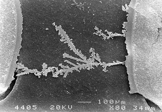
The chemical reactivity of fluxes is necessary to achieve optically and also functionally flawless solder joints. However, this reactivity can endanger the reliability of the product in the medium to long term. The essential effect here is electrochemical migration: the ions remaining on the circuit board become mobile through the action of moisture and attack the metallic structures. Due to potential differences, i.e. in any electronic circuit, successive detachment and migration of metal ions leads to the growth of so-called dendrites: These are tree-like structures that can grow from one contact to the next, eventually causing short circuits (Fig. 1). This process can take place within a few seconds or over significantly longer periods of time.
Meaning of standardized comb structures
Ever smaller PCB structures favor the underlying failure mechanisms. For the user, consequences such as recalls or product liability can be fatal.
Other types of contamination can arise, for example, from improper storage or handling, e.g. fingerprints (grease, salts), dust from the working environment, organic deposits, etc. Substrate supplier quality also plays a role here. Indirectly, any form of surface contamination can promote electrochemical migration, e.g. by reducing the adhesion of a protective coating and thus allowing moisture to penetrate.
Even without electrochemical migration, an electronic circuit can be functionally compromised if the surfaces of the assembly are not free of residue: Highly amplifying circuits, e.g. operational amplifiers, can already be caused to switch undesirably by leakage currents in the µA range.
These examples show that surface insulation resistance (SIR) plays an important role in assessing the long-term reliability of an electronic assembly.
The measurement of surface resistance on standardized comb structures is considered by solder paste manufacturers and industrial users to be a suitable tool for assessing the long-term chemical stability of the assembly.
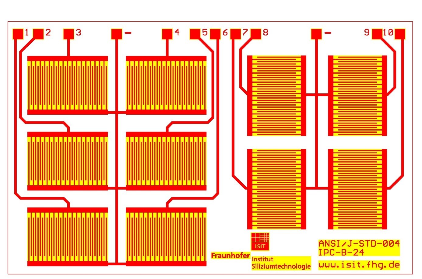
For this purpose, Fraunhofer ISIT offers an SIR PCB with 10 standard combs (Figure 2) and performs the corresponding surface resistance measurements. Up to 80 channels can be measured in parallel as standard.
Test conditions
The test conditions are specified in the international standards J-STD-004 (Requirements for soldering fluxes) and J-STD-005 (Requirements for soldering pastes).
According to IPC-TM-650 (ANSI/J-STD-004 / 05), the surface resistance test is performed under the following conditions:
Bias voltage: 45-50V
Measuring voltage: 100V
Climate: 85% rLF, 85°C
Test duration: 24h, 96h, 168h
A minimum surface resistance value of 100 megohms is prescribed as the limit value for the entire duration. The test conditions are often also modified by customer requirements to the corresponding application (e.g. use of lower voltages, such as 24V or 5V; use of other climates, e.g. 92% rLF, 40°C or climate change stresses).
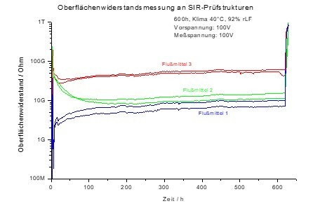
The fluxes/solder pastes to be tested may behave very differently with regard to the absolute value of the surface resistance or with regard to the curve progression (tendency: falling, constant or rising - see Figure 3 - exemplary SIR curves for 3 different fluxes).
Quality assurance of the comb structures
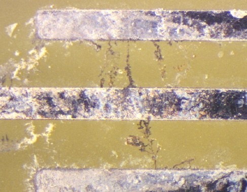
After the climatic test, the ridge structures are examined for changes (especially dendrite formation). Growth of dendritic structures is not allowed (see Figure 4) and is therefore a rejection criterion.
The standard SIR test is usually performed on the unpopulated board to describe the properties of the solder (flux in various solder configurations - solder paste, wave solder flux, solder wires).
Furthermore, on unpopulated boards, it is additionally possible to check the quality of cleaning processes or the effectiveness of passivation processes (e.g. covering by protective lacquer layers) by means of the surface resistance test. The measurements described qualify the long-term properties of the soldering, cleaning and lacquering media under climatic stress.
Not taken into account here is the influence of the component geometry (distances, gaps, capillary effects, etc., real local flux quantity and distribution), as well as the influence of secondary materials (component surfaces, topography, interactions, impurities, etc.). For this purpose, the SIR test structures can be directly adapted to the footprint design of the components or positioned directly under components. For this purpose, special standardized test PCBs are offered
(e.g. IPC B-36, IPC B-52), which can also be measured with the existing structure.