 Fraunhofer Institute for Silicon Technology
Saskia Schröder & Magdalena Kontek
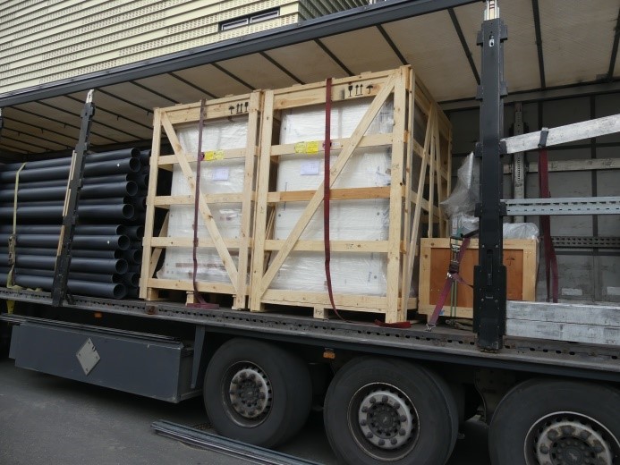
Delivery of the newly developed precision assembly machine as part of the FMD project
With the support of the Research Fab Microelectronics Germany (FMD), Fraunhofer ISIT together with the company ficonTec Service GmbH started the development of a new type of customised machine for precision assembly in 2017. This precision assembler enables the assembly of RGB light sources, taking us another big step forward in the direction of innovative optoelectronics. After a challenging and lengthy development of the individual functions and the interaction of the individual components, the new machine was delivered to Fraunhofer ISIT at the end of 2020 and successfully installed. Today, in our new TechBlog post, we would like to give you a close-up report of the machine and tell you about its special features.
Main Task: Assembly of RGB light sources
The task of the specially developed precision assembler is primarily the assembly of RGB light sources in order to take a further step towards optoelectronics. After a very demanding and lengthy development of the individual functions and the interaction of the individual components, the system was delivered to ISIT in October 2020 and successfully installed.
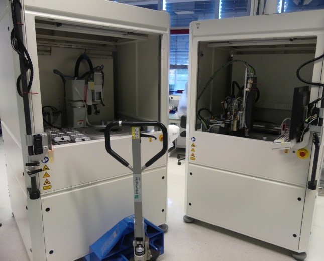
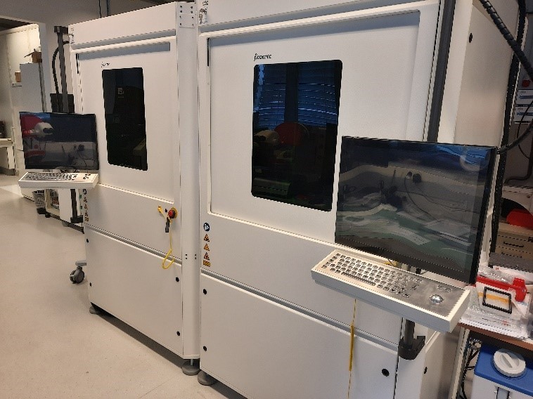
Since the desired functions that the system should be able to handle are too extensive for one machine housing, two housings of the same size were used and both machine elements were connected with transport slides.
Machine parts with clearly divided tasks
The left part (machine A) is equipped with a robot arm. It can remove various components from several waffle or gel paks as well as from sawn wafers and place them in a waffle or gel pack waiting on the transport carriage. Thus, the currently required components can be provided without an operator having to change a wafflepak. Various tools can be attached to the robot head, which can be used to remove parts from a wide variety of components. Both vacuum tools and grippers are available. In each case, a camera checks the position and rotation of the component being placed on the transport rail.
The carriage system is equipped with two 2" waffle paks, i.e. one can hold components ready in the assembly process, while the other can be loaded in parallel with new elements for the next assembly step.
The right-hand machine section (machine B) performs the task of assembly and connection technology. A placement head with exchangeable pick-up tools is arranged in the center. It can remove the supplied components that have been loaded from the left-hand machine section onto one of the transport slides. Substrate wafers, single substrates or panels in special holders can be placed on an 8" work table. A dispenser is installed for the application of various adhesives, and a special laser is mounted centrally under the work table for soldering the components onto the substrates. For the assembly of RGB light sources, a probe card holder was developed that controls the light sources during the assembly process and can thus switch them on and off. A measurement unit (BCT) that verifies the correct superposition of the light beams was also used. This helps to align the superstructures in the active state and thus to fix them optimally.
Precise work steps
The following steps are involved in setting up an RGB source: In the first step, a component is taken from a wafflepak or wafer and transferred to a transport wafflepak. This is transferred from machine part A to machine part B by a transport carriage and, after adhesive has been dispensed at the appropriate location, placed on a substrate with the precision placement head or soldered on with the laser. These processes are repeated until all components are present on the substrate (e.g. light sources, prism, diodes, etc). Then the probecard is moved to the connections of the substrate to activate the light sources. Now the necessary lenses are held between the light source and the already applied prism with the placement tool and their final position is determined with the help of the BCT. This is done by measuring the light beams and repeatedly correcting the lens position until an optimum result is obtained (active alignment). Only then is the adhesive applied to the substrate for the lens, which is placed in the depot and fixed by UV light. The complete component is then measured and the data stored in a database. Several camera systems monitor the processes and carry out the various adjustment steps.
The system is delivered with a fully written and tested program for carrying out the process steps described. This program is currently being worked on together with ficonTec in order to be able to manufacture light sources and other precision components as soon as possible.